Boiler Control System Programming
Boiler control system programming and
panel design fall hand in hand. Building and programming a boiler control system that
meets NFPA85 code requirements is very challenging. Just a few examples are interposing relays, a watch dog timer, the handshake between the Burner Management System and the Combustion Control System and performing critical input checks once a minute to verify the PLC input cards do not have stuck bits. Further, design requirements will call for things like having the wiring fail safe (on is a good state), high voltage AC and low voltage DC separation, PLC power requirements and total wattage heat dissipation.
Programming for a boiler control system takes a lot of years to learn and should never be attempted without a thorough understanding of how boilers work as well as what needs to be accomplished and lastly how to program with the PLC platform chosen.
To explain the fundamental logic we can use a fully metered cross limited combustion control system as an example. The principal function of this type of system is to have the air always lead the fuel when increasing the firing rate and follow behind the fuel when decreasing the firing rate. This will prevent the boiler from going into a rich condition during load swings. Programming cross limited systems is accomplished by using a high select for the air set point (fuel flow or boiler master) and a low select for the fuel set point (air flow or boiler master). There will be oxygen trim loop which is changing (multiplier) the characterized air flow to add or subtract from its measurement and force the fuel to react by cross limiting the set points and maintain proper
boiler tune.
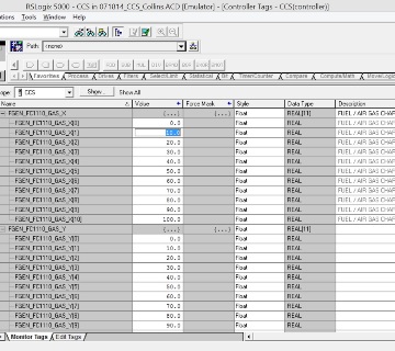
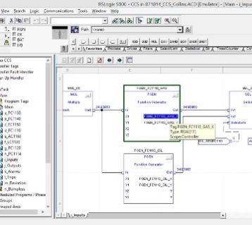
The air flow measurement will have a function generator for characterizing the
transmitter reading from minimum fire to 100% span so the X or input values will be adjusted and the Y or output values will be scaled in eleven steps from 0 to 100%.
The flow control outputs for fuel and air will also have function generators and are characterized from minimum fire to 100% span so the X or input values will inversely be scaled in eleven steps from minimum to 100% while the Y or output values will be appropriately scaled for the controlling devices during the tune.
These three function generators are always or should always be found on fully metered systems. To explain why these three function generators should always be used instead of only the air flow requires understanding loop tuning and could lead to a debate but through years of experience we have found it is best to have all three. Other characterization requirements are the set point for oxygen trim which is driven from gas flow and characterizing the fuel gas re circulation (FGR) if so equipped. Lastly there may be characterization for air flow related components like the fresh air inlet damper, windbox damper and the fd fan VFD. If running on oil there has to be a separate set of function generators for each oil controlling device as well.
Minimum
Safety requirements should be but are not always limited to tripping if a bad quality condition exists for air or fuel flow and if the fuel to air flow set points deviate a specified amount (in a running rich condition) for a short timed period. There are other reasons one may need or prefer to have the boiler trip but these are the most important.
There are many more functions that need to be addressed when programming a boiler combustion control system and it is easy to see why it is important to have it done by professionals with a proven track record. Having a bulletproof panel ready to go before the
boiler installation and
commissioning has been completed is a big time saver.
Collins Combustion offers programming services,
engineering services and
startup services for any type of boiler control system.
back to our Services page.